Project
ReNU - Collegiate Wind Turbine Software + Electrical Lead
- Embedded
- PID Control
- MPPT
- Power Electronics
- Team Lead
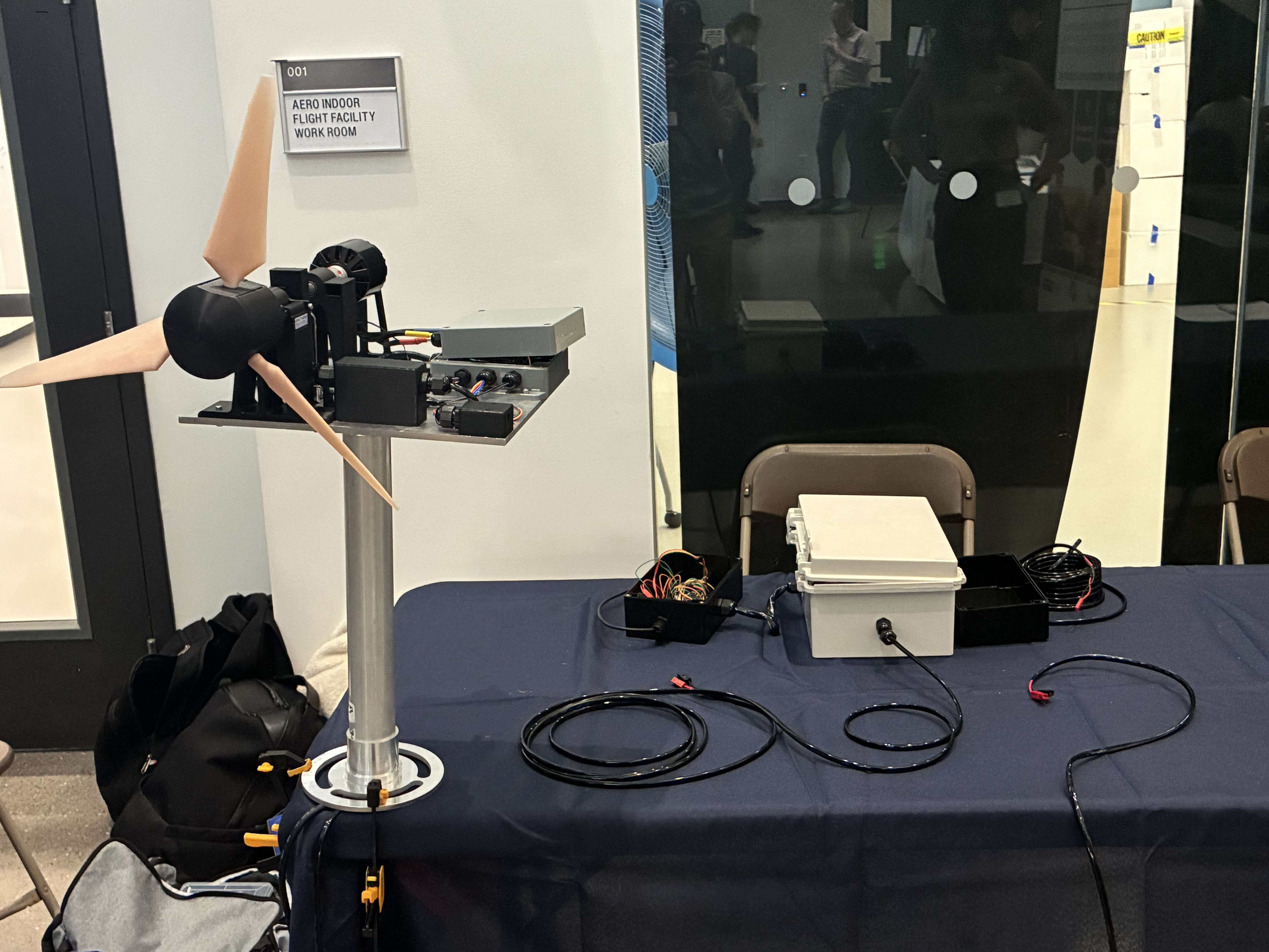
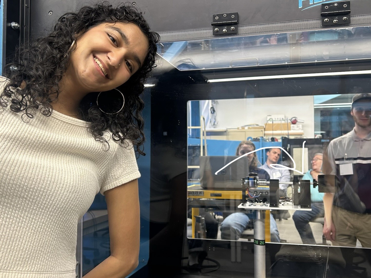
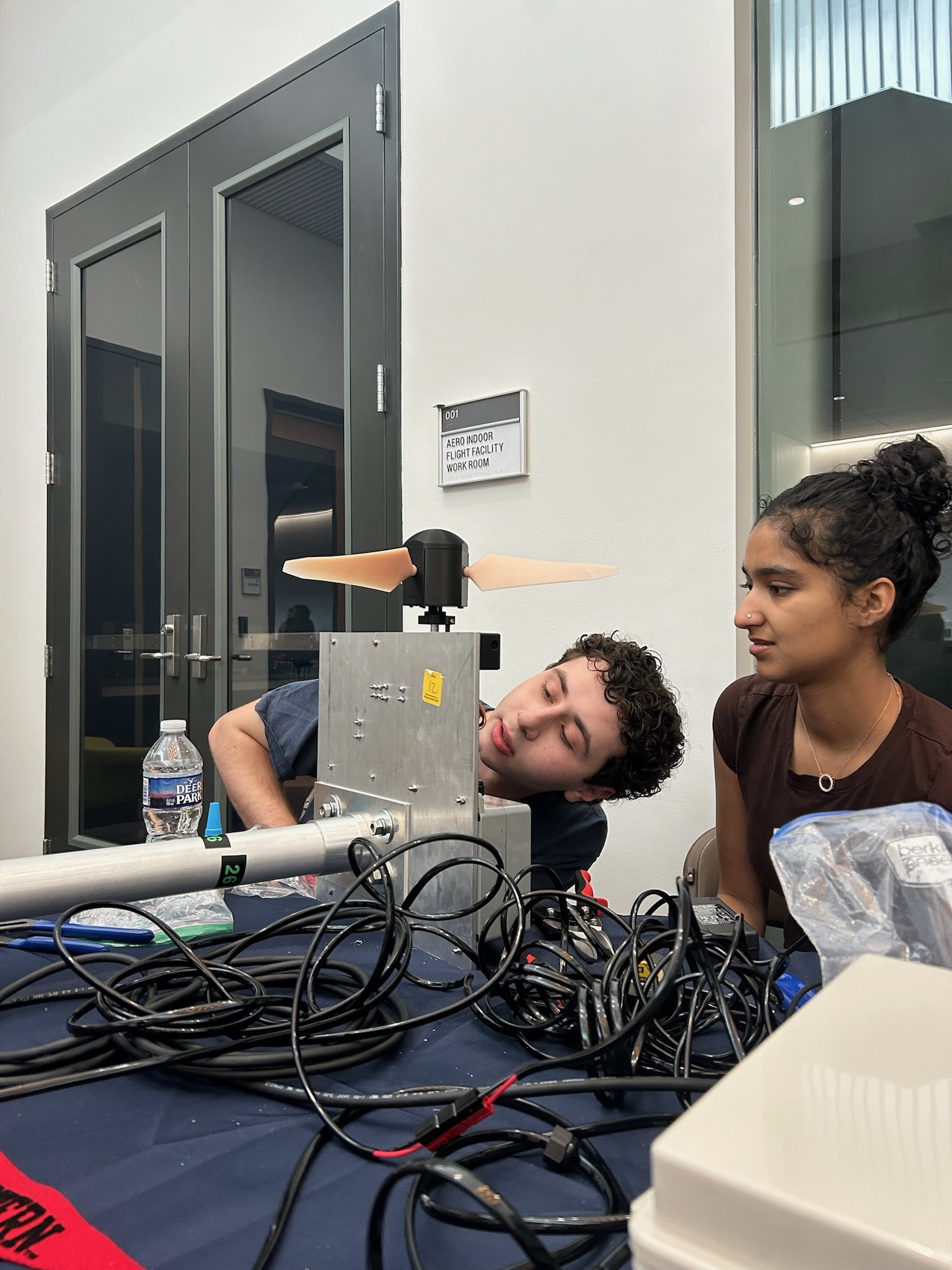
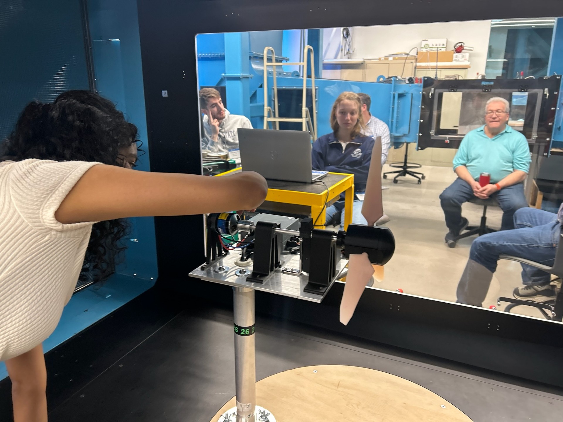
ReNU is Northeastern’s Sustainable Energy Club. In 2026, it competed in the U.S. Department of Energy Collegiate Wind Turbine Competition. As Software + Electrical Lead I designed the full power and control stack including rectification, MPPT load control, and closed-loop pitch control. I led a 6-person electrical/software team, and the product placed 4th-place at the Colegiate Wind Competition 2026. I made all schematics and diagrams on this website.
Overview
Led a 6-person team, designing the full power and control stack: 3-phase full-wave rectifier, MPPT load control, and a closed-loop PID pitch control system driven by tachometer feedback. Regulated rotor speed across 5–15 mph wind. Placed 4th of 32 teams at the DOE Collegiate Wind Turbine Competition 2026.
Electrical Top-Down
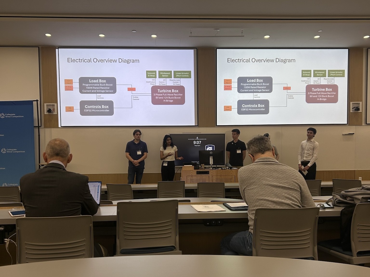
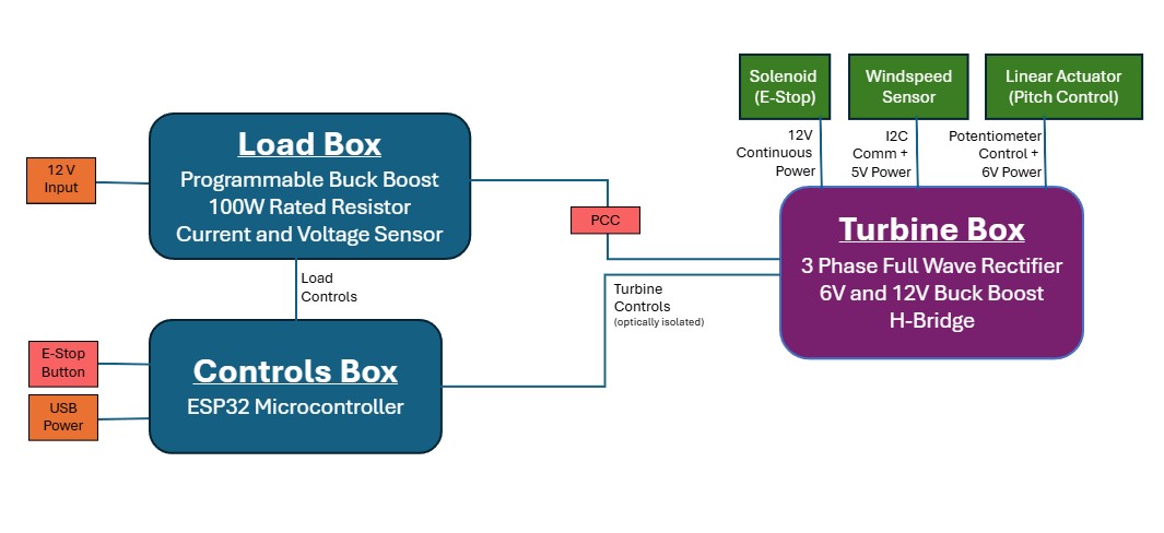
The power stack moves the generator output through a 3-phase full-wave rectifier and into an MPPT-controlled resistive load that continuously seeks the turbine’s max-power point. Voltage, current, and tachometer-pulse sensing feed back to the MCU, which arbitrates between load tuning and pitch actuation.
For a more detailed breakdown of the parts, go to the Parts Overview section below.
Software Top-Down
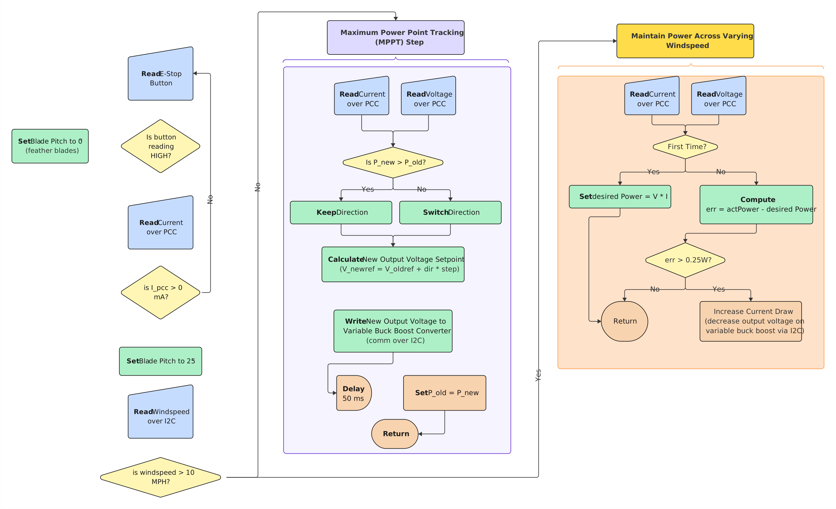
Two cooperating control loops run on the MCU: an MPPT loop that follows the turbine’s power curve by adjusting the resistive load, and a PID pitch controller driven by tachometer feedback that holds rotor speed steady across the 5–15 mph operating window. Both loops share the same sensor pipeline and arbitration logic.
Parts Overview
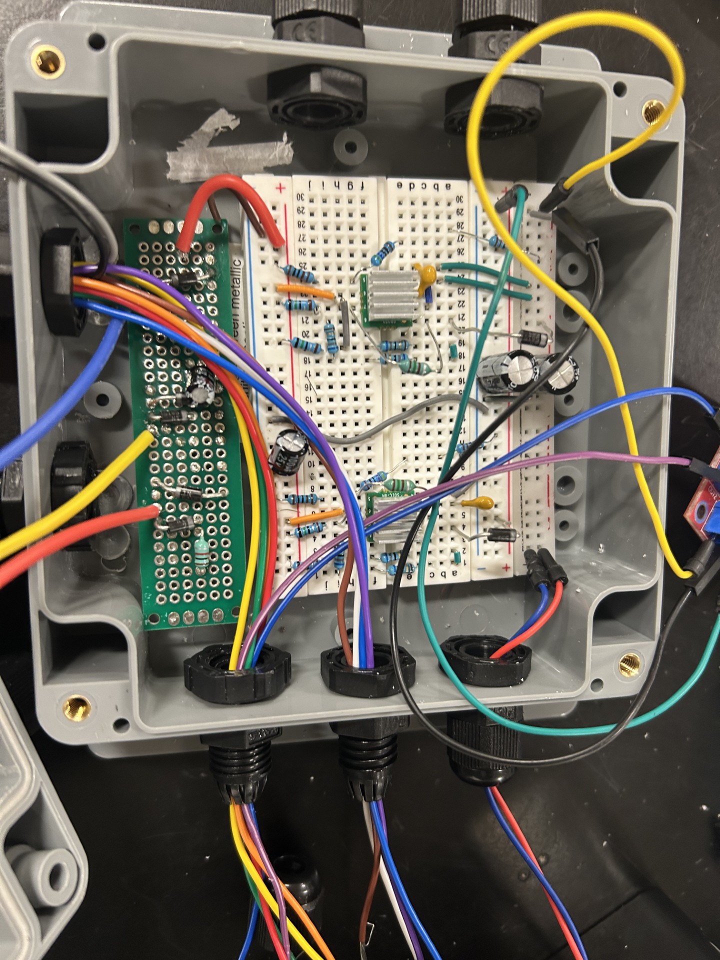
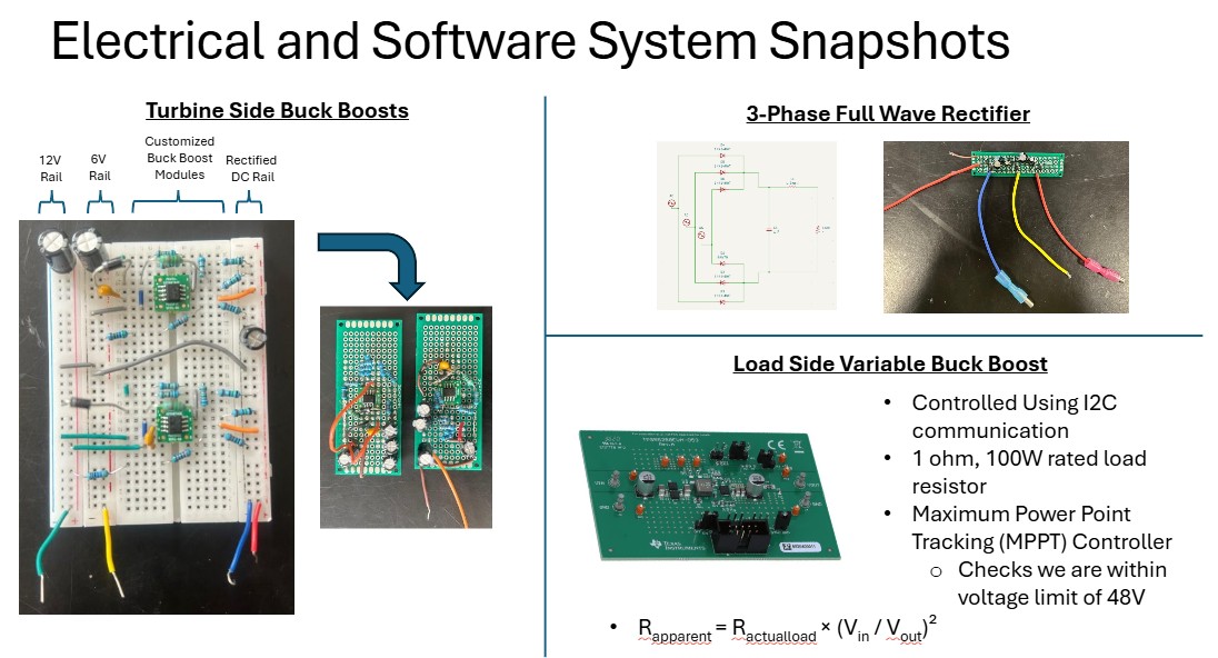
The top right shows the 3-phase full wave rectifier that turns the generator AC output into DC. This is fed to the turbine side 6V and 12V buck-boosts shown on the left half to power the onboard sensors and motors (the linear actuator, windspeed sensor, and solenoid). The originial rectified DC rail is then fed into a programmable variable buck boost (on the bottom right) on the load side.
These are the primary components of the electrical system, apart from smaller voltage and current sensors and an ESP32 microcontroller that controls the entire system. Refer to the previous Electrical Top-Down section for details on placement of the components in the overall system.
More on Power Control System
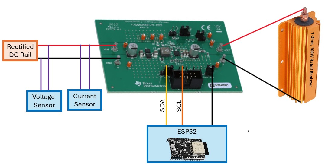
As shown below, on the input end of the buck-boost is the rectified DC rail and on the output end is a 100W rated resistor. Even though there is a fixed resistance at the output end of the buck-boost, by altering the duty cycle of the switching transistor of the buck-boost through software, and thereby altering its output voltage, we can alter the effective load impedance presented to the generator. This allows us to control the power generated to either the maximum power point or a controlled operating point.
By altering the buck-boost output voltage across the fixed resistor, we change the output current (I_out = V_out / R_load), which changes the output power (P_out = V_out^2 / R_load). Since power must be conserved through the converter (P_in ≈ P_out), changing P_out forces a corresponding change in input current drawn from the rectified DC rail. Since power is conserved, the effective load resistance can be calculated as:
Maximum Power Point Tracking (MPPT) Mode:
Since the generator has internal impedance, its output power vs. load curve has a peak, known as the maximum power point, at a specific R_eff. By sweeping V_out and measuring rectified V_in and I_in, you find the V_out setpoint that maximizes generator power output. In this way, the buck-boost maximizes the power extracted from the wind. The software details are in the Software Top-Down section above.
Maintain Constant Power Mode:
Since the generator has internal impedance, its output power vs. load curve has a peak, known as the maximum power point, at a specific R_eff. By sweeping V_out and measuring rectified V_in and I_in, you find the V_out setpoint that maximizes generator power output. In this way, the buck-boost maximizes the power extracted from the wind.
KiCAD Schematic
What I learned being ReNU's Software/Electrical Technical Lead
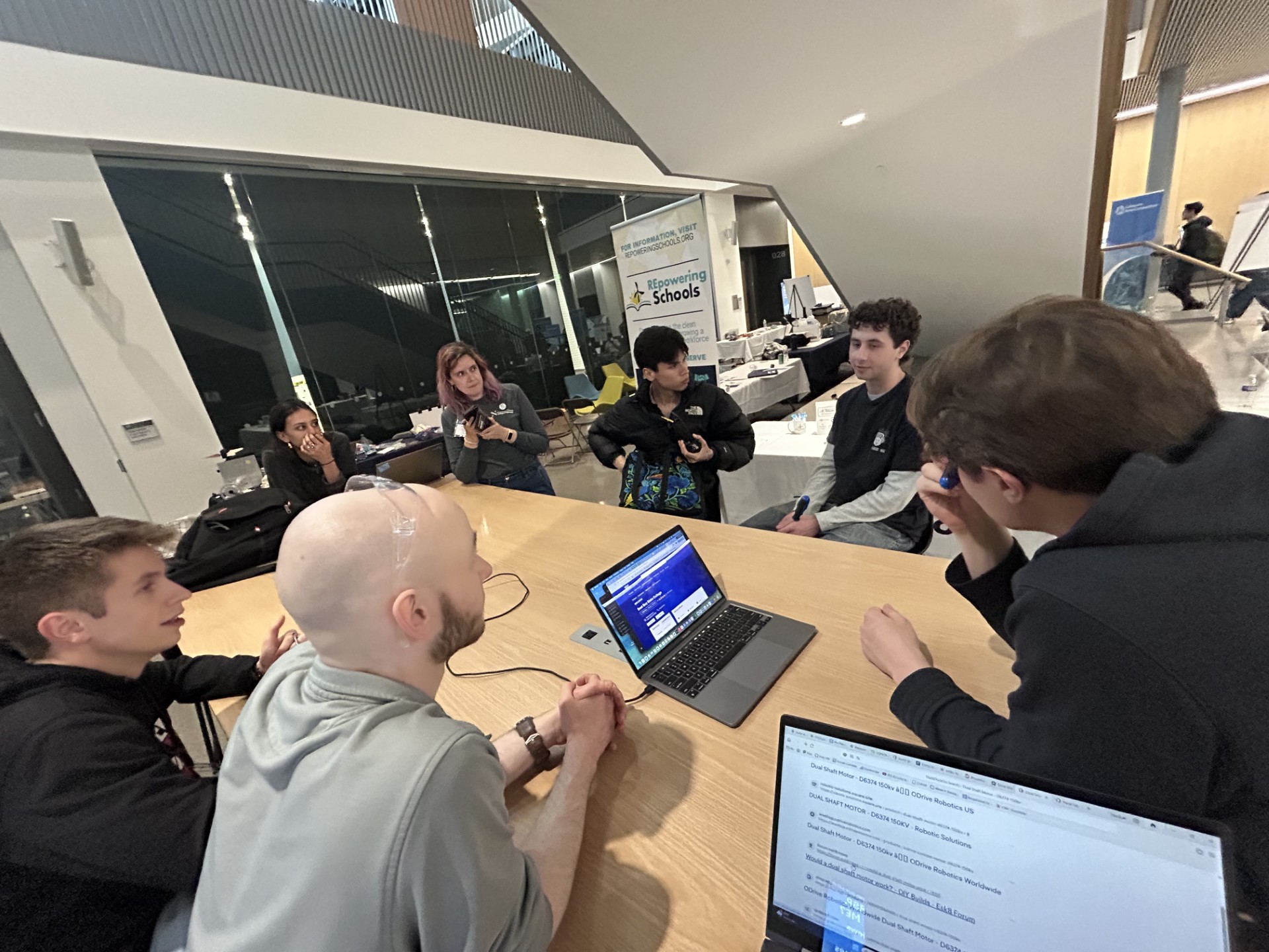
For this project, I collaborated with electrical, computer, and software engineers to design and implement the control and power systems for the wind turbine. Having a background in both electrical and software engineering allowed me to bridge the gap between the two domains and allowed me to devise the system architecture. Additionally, I learned a lot on leading a team. Once the top-down schematics were loosly completed, I assigned tasks to team members based on their expertise. For example, many EECE engineers were put on the load design and component research, CE majors were assigned to interface the microcontroller with the TPS55288 module and windspeed sensor, and CS majors were assigned to develop the control algorithms such as MPPT and PID.
Additionally, I worked across teams, communicating heavily with the Mechanical Engineers, Physics Majors, and Data Scientists. For example, the E-Stop required opinions from both electrical and mechanical perspectives, the sensor and motor placement was crucial to both the structural team and software team, and choosing which generator to use required physics knowledge and electrical engineering expertise that many multi-disceplinary teams contributed to.
One difficult aspect was ensuring proper integration of all subsystems. Often, the development timelines did not align, requiring teams to simulate and test their components in isolation before integrating them. Tools like LTSpice were crucial in simulating the behavior of the system under various conditions, even if we could not replicate the exact same environment yet.
Tuning a PID loop in front of a wind tunnel is very different from simulating one. The biggest lessons were about disturbance rejection, sensor noise, and how much of a control system's reliability comes from clean wiring, debounced signals, and conservative gains